Lightning Protection Standard
IS/IEC 62305 is identical with IEC 62305 “Protection against Lightning “ issued by the International Electrotechnical Commission ( IEC ) was adopted by the Bureau of Indian Standards on the recommendation of the Electrical Installations Sectional Committee and approval of the Electrotechnical Division Council.
IS/IEC 62305 : 2010 supersedes IS 2309 : 1989 “ Code of practice for the protection of buildings and allied structures against lightning”.
IS/IEC 62305 deals with the protection. In and around a structure, against physical damage and injury to living beings due to touch and step voltages.
Lightning Protection System as per IS/IEC 62305 consists of both external and internal lightning protection systems.
The external LPS is intended to intercept direct lightning flashes to the structure and conduct the lightning current from the point of strike to the ground. The external LPS is also intended to disperse this current into the earth without causing damage to the structures or causing unsafe potential rise / sparking.
An internal LPS protects equipment against transient voltages and currents.
Major Changes in the IS/IEC 62305 :
Lightning Protection System Methods :
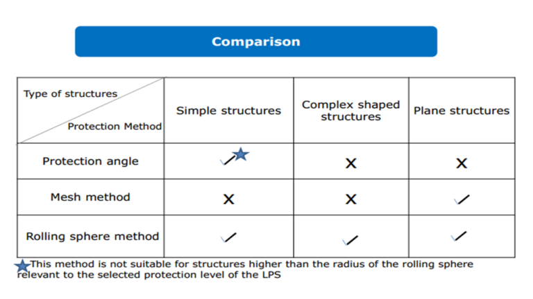
Acceptable methods for designing the lightning protection system as per IS IEC 62305 :
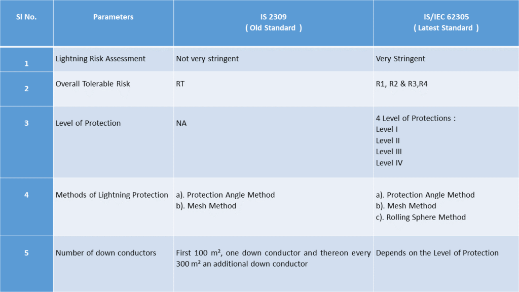
a). Protection Angle method – suitable for simple structures or for small parts of bigger structures. This method is not suitable for the structures higher than the radius of the rolling sphere relevant to the selected protection level of the LPS.
Air-termination rods should be positioned so that all the parts of the structure to be protected are inside the envelope surface generated by projected points on the air-termination rods to the reference plane. The protection angle should confirm to the table mentioned below, with h being the height of the air-termination above the surface to be protected.
Note 1 : The protection angle method has geometrical limits and cannot be applied if H is larger than the rolling sphere radius, r.
Note 2 : The angle will not change for values of H below 2 m
Note 3 : H is the height of the air-termination above the reference plane of the area to be protected.
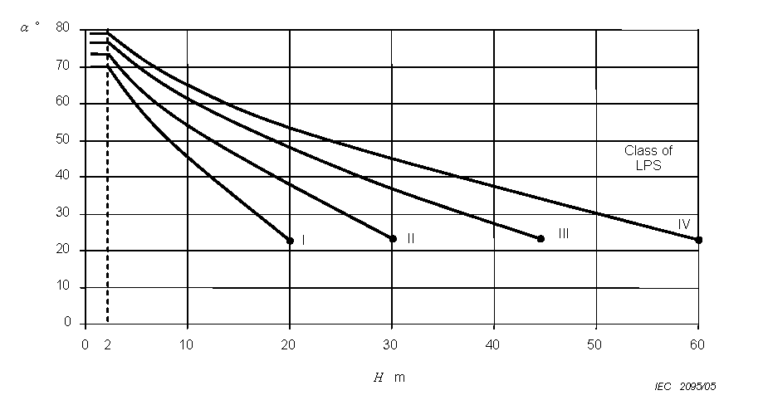
H : Height of the building over the ground reference plane
h1 : Physical Height of an air termination rod
h2 : h1 + H, being the height of the air termination rod over the ground
Mesh Method :
Suitable for the protection of plane surfaces. The choice of the method depends on a practical evaluation of its suitability and the vulnerability of the structure to be protected.
Mesh method is considered to protect the whole surface if the following conditions are fulfilled –
a) Air-termination conductors are positioned on –
- roof edge lines
- roof overhangs
- roof edge lines, if the roof slope exceeds 1/10,
- the lateral surfaces of the structures of the structure
higher than 60 Mts at levels higher than 80 % of the height of the structure.
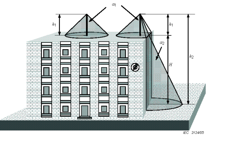
b) The mesh dimensions of the air termination network are not greater than the values mentioned in the below mentioned table.
Table 2 - Maximum values of rolling sphere radius, mesh size and protection angle corresponding to the class of LPS
c). Rolling sphere method – suitable for complex shaped structures
Applying this method, the positioning of the air-termination system is adequate if no point of the volume to be protected is in contact with a sphere of radius r, rolling on the ground and on top of the structure in all possible directions. Therefore the sphere should touch the ground and / or the air-termination system.
The radius r of the rolling sphere depends on the class of LPS. In case there are two parallel horizontal LPS air-termination conductors placed above the horizontal reference plane, the penetration distance ‘p’ of the rolling sphere below the level of the conductors in the space between the conductors may be calculated :
P = r – r² – (d/2)²
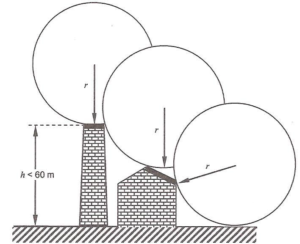
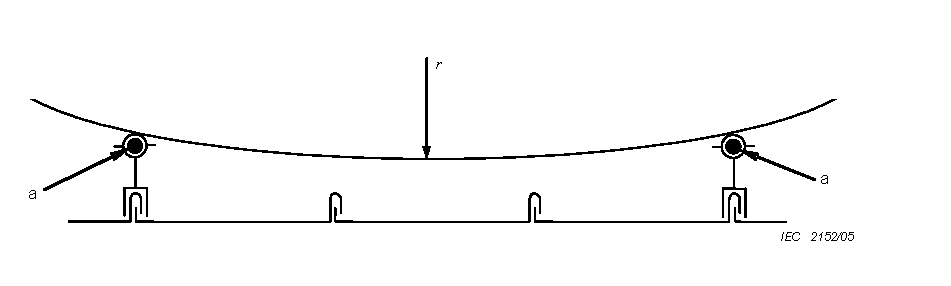
Note : The penetration distance ‘p’ should be less than the physical height of the air-termination rods above the reference plane minus the height of the objects to be protected.
Best Suitable Method :
Down Conductor System :
In order to reduce the probability of damage due to lightning current flowing in the LPS, the down-conductors shall be arranged in such a way that from the point of strike to earth :
- Several parallel current paths exist
- The length of the current paths is kept to a minimum
- Equipotential bonding to the conducting parts of the structure is ensured.
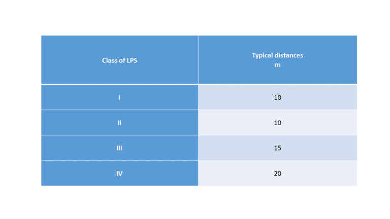
Typical values of the distance between down-conductors according to the class / level of protection :
Equipotential Bonding :
It is imperative that LPS components with the other conductive parts are the standards to reduce the potential differences caused by the Lightning current. Equi-potentialization is achieved by interconnecting the LPS with structural metal parts, metal installations etc. International Standards recommend interconnection of all the earth electrodes in a system.
It is recommended to interconnect all the earth electrodes in a premise to achieve uniform GPR in case of any lightning or abnormal voltage conditions. All individual earth pits in the facility made as above shall be interconnected to form equipotential earth system. Typical illustration bonding recommended is given below.